- Picks
- Shovels
- Paint
- ¼” paint brush
d) Staff members
- Topographer
- Measuring technician
- Rodman
- Stake man
- Brush cutter
- Auxiliary staff
e) Determining the initial level of the platform
- Select a place with sufficient visibility near the intake weir in which to
place the level station
- Fit the level rod in the river bed opposite the catchment area and take
the corresponding reading
- The initial level of the platform is the difference between the first
reading taken in the previous step and the highest level of the
headrace channel
f) Layout of the platform
The layout of the platform consists of a number of stakes placed in the
ground between the intake weir and the forebay tank.
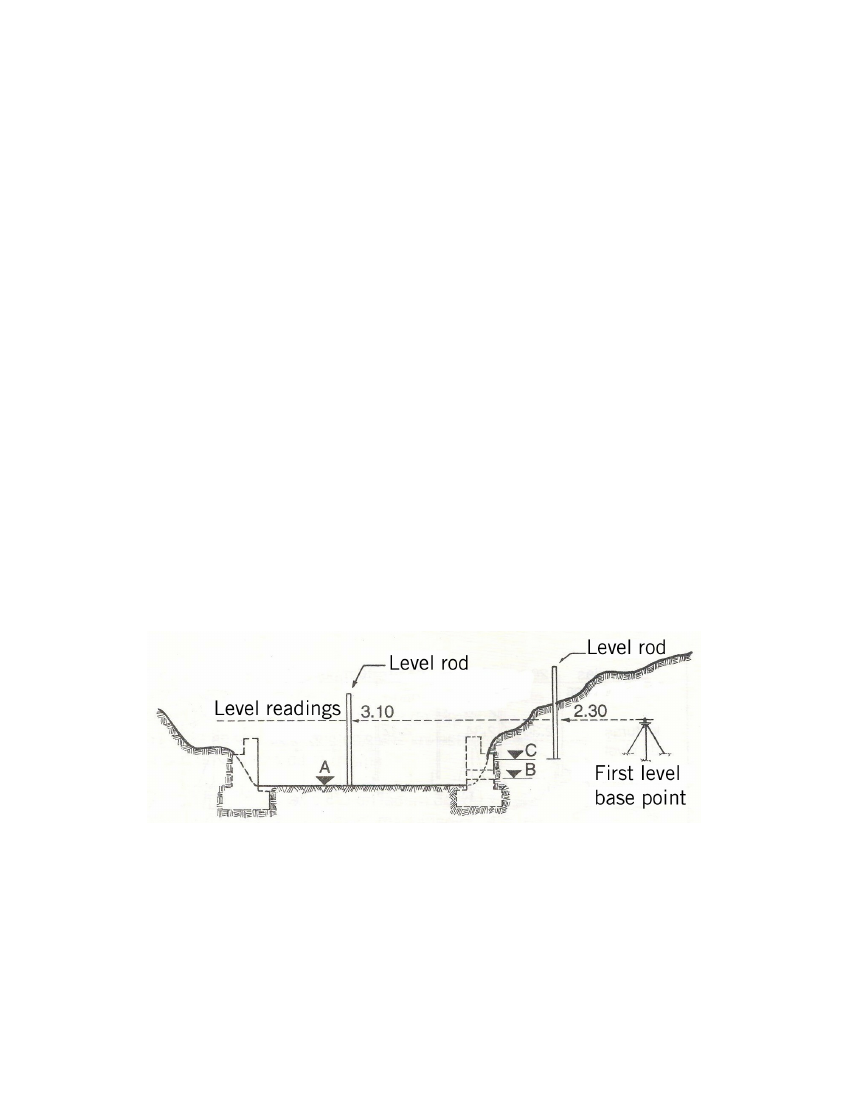
A = Level of the river bed
B = Level of the bottom of the catchment area
C = Highest level of the headrace channel
For example, if it is assumed that in the corresponding plan the levels are A =
3,100 m.a.s.l (metres above see level).; B = 3,100.30 m.a.s.l. and C = 3,100.80
m.a.s.l, then calculate the difference in elevation between A and C (0.80m).
Make a note of the 1st reading (3.10m), then the reading for the initial level of the
platform (3.10 – 0.80 = 2.30m).
Fig. 18
19